
Friday, 22 October 2010
Final Head
Here's the final head without hair.
 Overall the basic shape is there but I would have liked to have had more time spent on the texture and also getting the right shade on the ears.

Specular painting
In Photoshop the bump and colour maps were used to create specular highlights. Various brush sizes with a very low opacity in lighten mode were used to paint in the specular highlights before being blurred with a gaussian blur filter and added to the specular map in the material editor in max.

A further sandstone texture was ading in Photoshop to enhance the effect.

Texture painting
Using Photoshop, the colour map had a bump texture applied to simulate skin, this was then added to the material editor within max as a bump map.


Different values were then used to get the right texture in max

Texture painting
The final UVW map was opened in photoshop and by cutting and pasting parts of the skin from the original photo onto the map the foundations of the skin was laid out.
This new map was the aplied to the head in 3ds max using the material editor. By setting up a script within Photoshop I was able to keep updating the material.

This new map was the aplied to the head in 3ds max using the material editor. By setting up a script within Photoshop I was able to keep updating the material.

UVW mapping
To allow a skin material to be added to the head a UVW unwrap modifier was applied to the head. This was to allow the map to be layed out flat.
This stage proved to quite difficult as the map come out rather squashed up and took a lot of time fiddling to pull out the individual vertices into the correct place. Use of a checkered bitmap helped to show that the polygons were more or less in the right position


This stage proved to quite difficult as the map come out rather squashed up and took a lot of time fiddling to pull out the individual vertices into the correct place. Use of a checkered bitmap helped to show that the polygons were more or less in the right position


The ear

The same process was used as that of creating the head model.

Modelling rest of head
The back of the head modelling was based on using a sphere which was placed in position. The parameters were altered to bring the amount of polygons down to an equilibrium with the face. The excess poygons around the base were then deleted. Using the snap tool the vertices between the face and the sphere were lined up and welded together.

The edges of the poygons at the base were then pulled out using the shift tool to create new ones, and manipulated into the right shape.

The edges of the poygons at the base were then pulled out using the shift tool to create new ones, and manipulated into the right shape.
Symmetry
The next stage was to add a symmetry modifier to make the face whole. The open edges on the side to be joined were selected and scale tool used to straighten them out befor asdding the symmetry modifier.


Tuesday, 5 October 2010
Filling in the quads
Using the line tool in 3DS Max, the quads which were drawn out in Photoshop were mapped out. At this stage I realised that I hadn't formed any triangles, but I had formed a pentagon which I translated back into two quads. The mapped out quads were then converted to editable polys, attached together and then the vertices welded to create a solid shape.


Setting up the Reference Plates
The final topology images were assigned to planes within 3DS Max and adjusted to the correct size and direction.

Topology: Spiderman mask
Using Photoshop (blue) lines were painted over the facial features to create a topology. 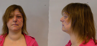 These lines were then further broken down into (red) quads. Trying to determine in which direction the lines should flow was quite tricky from the 2D reference. By using refernce images of the underlying facial muscular structure and looking carefully at the prominent features of the reference photos I believe that I have managed to pick out the important features.

 These lines were then further broken down into (red) quads. Trying to determine in which direction the lines should flow was quite tricky from the 2D reference. By using refernce images of the underlying facial muscular structure and looking carefully at the prominent features of the reference photos I believe that I have managed to pick out the important features.
Thursday, 23 September 2010
Preparation
The chosen reference photos (1 side view and 1 front view) were opened up in Photoshop. This is for the initial preparation of them to be used for reference plates within 3ds max.
(add image)
The first step was to straighten up the images and correct any barrel distortion caused by the camera lens / photographer. This was achieved through the use of the lens correction filter(filter>distort>lens correction) . The images were corrected by using the straightening tool, then altering the values of the 'remove distortion', 'horizontal perspective' and 'vertical perspective' sliders. These changes were then applied and guidelines placed over the features to help line up the two images. The transform tool was used to make any adjustments required.


Yr3/S1:
WEEK 1
The first 5 weeks of this semester will be concentrating on organic modelling of a head from a reference photo, with the aid of an online tutorial available at: http://cg-india/tutorials/3dsmax_tutorials_organic_modeling.html
The remainder of the time will involve working in a small group to a brief given by a representative from visitessex.com
Subscribe to:
Comments (Atom)